QFD
During our QFD process, we determined that it would be best for us to be able to pick up both cubes and cones, ideally in any orientation. This is critical for being a team that can complete links on the upper levels, and be compatible with other teams. Making it simple was important to us, in order to minimize issues and make assembly quicker. It was also determined that the rigidity of the gripper is incredibly important, as it is the most exposed part of the robot, but it still had to be light enough to not have significant issues when being used with an arm. It needed to be modular and easy to work on in the case of an unfortunate incident.
Design and Prototyping
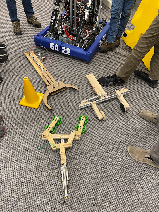
We began the design process by brainstorming as many different mechanisms that could be used as a potential intake. Taking the most promising ideas, prototypes were made in order to determine the physical capabilities of each design. The three main concepts stood out as being simple and robust, while still staying lightweight enough to not affect the movement of the arm. A late prototype design was created using solidworks, and cut out of ¼ in mdf sheet. The prototype was mounted to the arm, and tested until it was decided that it would work well in the final design.
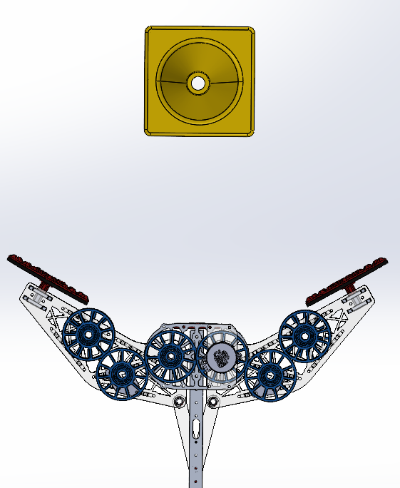
The design of the gripper utilizes a pneumatic piston that is embedded into the arm for actuation. The clever linkage design allows for maximum force on the game piece when the gripper is more closed, which helped make sure that both game pieces could be held securely without risk of damaging them. Discs that are free to rotate, which we like to call “pivot paws” allow for cones to be picked up off of the floor in odd orientations, while still being oriented properly for placement on any level. Wheel and motor mounts were added to the design as a precautionary measure in case we needed to change to an active intake. The addition of a lidar sensor made it possible to detect when a game piece was the proper distance, and allowed for automation of gripper closure
Final Assembly and Modifications
The final gripper was cut out of ¼ in polycarbonate on a CNC router. After assembly, a thin layer of drawer lining was added to each pivot paw in order to increase friction on the game pieces. In order to ensure that the gripper never extended beyond more than one plane of the robot (as per the game manual), small spacers were added to the shaft of the piston to increase the lower limit, thus making the overall opening width slightly smaller. One issue that arose was that the pivot paws led to inconsistencies when placing, as the cones would be swinging, making it difficult to predict their exact orientation. This issue was solved by locking the pivots, as we found that they were not really necessary. In all, the design proved to be effective in competition when picking up from the double substation, but slow from the ground. If we had more time, it would have been nice to integrate some sort of intake so that ground pickup could be faster, helping to adopt the “touch it, own it” mentality that seems to be critical for fast cycle times.