The Evolution of our Intake
QFD
The primary design issue this year was understanding how a game piece can be placed or moved to the poles and platforms, which were a fair distance from the center of the robot, even when pressed against the edge of the field elements. There are many design constraints that made this problem difficult to solve. First off, after reading the manual, and understanding the point values, it was decided that we wanted to try and place pieces at all 3 levels, which means that we wanted an arm that was long enough to reach all the levels quickly, ideally being able to move to any position in less than one second. It also had to be strong, and precise enough to place a cone on one of the poles. In a similar fashion, we decided that it would be sufficient to be able to pick up from the double substation with speed, but still be able to pick up from the floor if necessary, which drove a lot of the geometric decisions for the arm.
Design and Prototyping
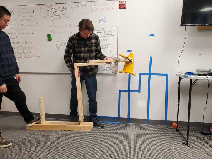
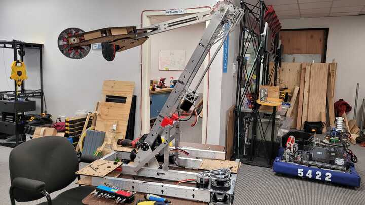
We began the design process by drawing up some geometry concerning the path the piece might need to take. There were two main mechanical systems that could be used, one being a pivot, and the other being a telescope. When used in conjunction, they are fast and reliable, but are quite complex to design. For this reason, we opted for a 2 pivot point, fixed length arm design for its versatility and simplicity. One unique part of the arm is the worm gear drive that is used in both joints. In order to reduce cost, we took apart two winches from Harbor Freight, which each had a worm gear and a spur gear that offered a 41:1 gear ratio. A neo with a 5:1 planetary gearbox was fixed to each joint, which made a total of a 205:1 gear reduction. This reduction offered the necessary torque while fitting well within the speed constraint of one second. The worm gear also simplified the software control of the arm, as it is non-backdrivable, which helped make implementation quick.
Final Assembly and Modifications
With our design ideas finalized, we then proceeded to start designing the arm on Solidworks. We machined both arms with 1/16 in aluminum tubing, with the upper arm having cutouts for the pneumatic piston and gripper. Initially we had several issues with the arm bouncing due to backlash in the worm gears, thus we implemented several changes over the course of 2-3 weeks including adding a gas strut damper, machining a new shaft for the worm gear which was a more proper fit, adding more grease, and replacing the bushings with thrust bearings. Once completed, the arm worked extremely smooth, with no backlash and incredible precision.
