Week 1 (1/7 – 1/14)
Button Board:
Last Friday we worked on redesigning the layout of the button board that software had created. We looked at the old button board (Deep Space 2019) to see what parts would need to be bought. Then we rearranged the layout of the button board.
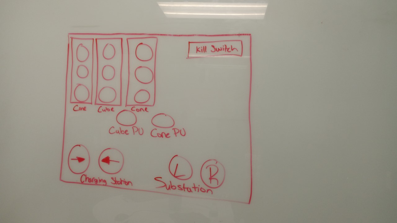
Originally, the substation and charging station buttons were diagonally opposite to each other, and the cube/cone pick up buttons were shifted more to the right.
We changed the layout to accommodate for the important function of picking up cones and cubes, and placed these functions in the middle of the button board. We decided to place the kill switch on the top right, as it was still an important function, but we didn’t want it to crowd the middle of the board. Also, we changed the charging station and substation buttons (used for approaching the charging station and docking into the substation respectively) to be placed at the bottom of the button board. One of the things that we kept the same, was the grid in the top left, which represents a full grid of nodes to place the cubes/cones. The main function of this grid was to show if the nodes on a specific grid were available for placement (shown through lighting/not lighting up) and to execute code to place the node on that specific node in the grid.
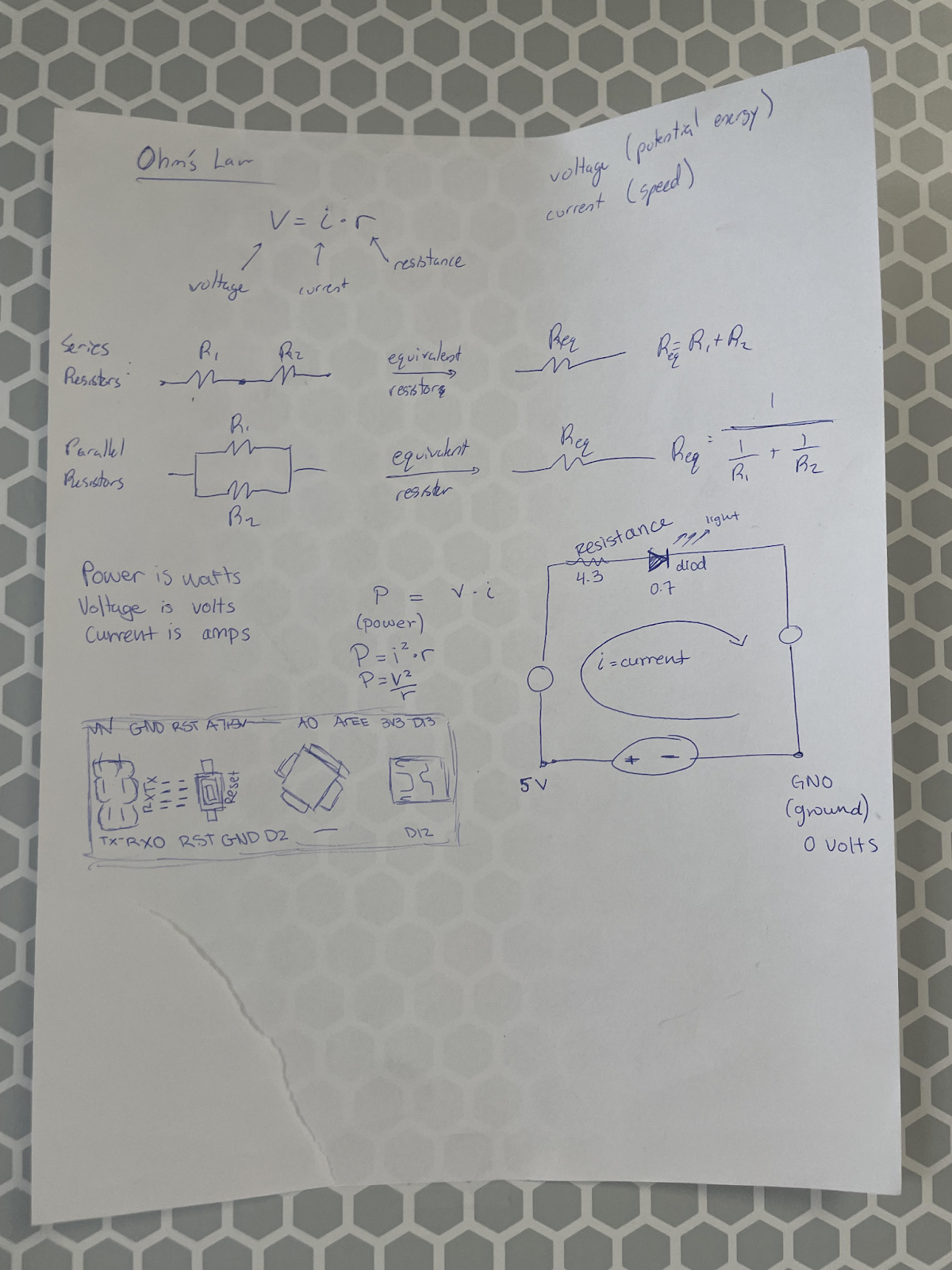
We also learned about the Arduino, to gain a better understanding of the button board. Specifically, we learned about Ohm’s law, and the equations associated with it, as well as the specifics on power, voltage, resistance, and current.
This Friday we learned about the different parts of the electrical panel, how they are used, and compared the components to previous years robots. On Saturday we drew out how we wanted the electrical panel layout to look.
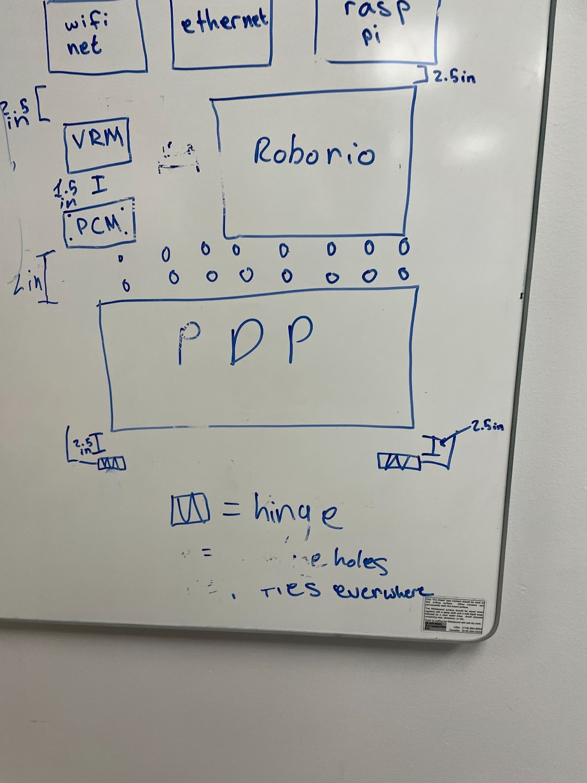
This is the design we came up with for the electrical layout. We came up with a layout which used the necessary electrical components, and assembled them in a way which minimized the amount of space used. Specific components were placed next to each other depending on function and communication between parts. After this was drawn, using SolidWorks, we began to CAD the design and discuss placement on the robot.
We finished wiring the encoders by splitting the power connection and making a chain of encoders throughout the robot. We encountered some issues with communication, but it was fixed thanks to the software subteam.